Sunday, March 22, 2015

N64 GC Replacement Stick Controller IC Swap MK2

Edit: Ahhh, didn't realise I would be hackaday'ed. I'll have the compiled hex files up as soon as I get to test the source works with the modifications. If you have an ATTiny261A spare, I'm happy for you to take the source and try it out. I should have the parts by Tuesday. In the meantime, using the ATtiny24 method still works perfectly fine, it's just a pain to solder.

Edit2: Compiled hex files - https://drive.google.com/file/d/0BxyIgc7ZORksdUhLNGdoTFJXQzg/view?usp=sharing


Using the method in this previous post you are able to replace the IC on these Simple Jet boards. The issue is the ATtiny24 only comes in an SOIC narrow variant. Looking through the ATtiny catalogue there also aren't any 18 pin SOIC variants available.

It's time to get crafty again. Looking around I found the ATTINY261A-SU which is a 20pin ATtiny variant for $1.58AU each in when you order a quantity of 2 from RS including shipping. So still quite cheap (you could use the more expensive ATtiny26 too).

The problem is that the chip itself has a layout of 20 pins.

Some simple analysis of the pin orientations allows us to pick an optimal layout. With this layout we can now do the following:


Sunday, October 26, 2014

N64 GC Replacement Stick Controller IC Swap

Edit: I'll shortly have code and instructions for using the wider ATTINY26-16SU/ATTINY261A-SU for easier soldering (order this rather than the ATtiny24 if you are looking to perform this mod in the next couple of days).

Edit 2: Here are the updated instructions!

Building on the awesome work of forum member "micro" from NFGgames in this thread, I decided to take things a step further and modify the board directly; instead of replacing the entire PCB from the replacement GC style joysticks (with the "Simple Jet" PCB). This was to bring down the cost of replacement from $20 to $2 (considering you have already paid for the board in the original stick) and to satisfy those waiting for limited release of these PCB's (myself included).
The only real downside to this modification is you don't get the updated joystick potentiometer or easy to configure jumpers.

While some suppliers have released a newer version of this stick, you aren't guaranteed that you will receive it from all suppliers, they have also increased the price of this version and there are still minor issues with these sticks that micro's redesign has fixed. This swap will also work for that board too, by just removing the components in the same positions.

Micro's mod relies on the ATtiny24/24A. The great thing about the chip is it has a highly configurable pin layout. Through some simple reverse engineering of the original board, reconfiguring the code's pin dependencies and some chip reorientation, I have been able to get this to work by removing a couple of passives on the original board and replacing the existing IC with the ATtiny24. You can either use the SOIC based ATtiny24 or ATtiny24A (whichever is easier to source), as they are identical for this purpose except for minor current requirements.


Tuesday, November 19, 2013

Supermicro BIOS Shenanigans

Let me take you on a small journey. You receive a large number of Supermicro workstations with X9SRG-F boards. You get them connected and racked up, try to install something and the keyboard doesn't work. You try another, same thing.

OK, it's a USB keyboard, maybe there is a problem with the BIOS reading USB, I'll just plug in a PS/2 keyboard. Oh there isn't a PS/2 port on this board. Right lets try IPMI to get into the BIOS using the console. Great, this works, but you cannot mount any USB devices at all. I'll just plug in a SATA drive and get the BIOS flashed to see if it's something up with the BIOS.


Tuesday, July 2, 2013

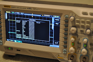
Rigol DS2072 200Mhz Bandwidth and Full Option Hack


UPDATE:

You can now generate keys and permanently activate all of the options and bandwidth without any extra hardware. Here is the c code which will generate the keys (it is the most up to code from the thread with a couple of modifications). All you have to do under Linux is place the above code (and fill out the private key value from the forum or use the pastebin link's code) into rigolkey.c. Alternatively there is also a Windows exe floating around on the forum there too which you can use.  

Make sure you have g++ installed and perform the following:
mkdir miracl
cd miracl/
wget https://github.com/CertiVox/MIRACL/archive/master.zip
unzip -j -aa -L master.zip
bash linux (or bash linux64 if running 64bit OS)
cd ..
gcc rigolkey.c -I ./miracl/ ./miracl/miracl.a -o rigolkey

Now run:
./rigolkey [your device serial] [option parameter]
Use "DSA9" for the option parameter to convert to a DS2202 with all options enabled. There are more options available here. The device serial number is located on your about screen, or on the back of the scope. If you have somehow managed to reset your serial number to a default value on the about scree (DS2A0000000001), then use that rather than the sticker at the back.

It is recommended to have at least firmware version 00.01.00.00.03 before entering the licence. Now apply the licence key that the keygen spits out. This is located under Utility>Options>Setup>Editor=ON. Enter the code using the intensity dial and button then hit Apply. It should then say "Option Installed!" if you entered this correctly. You now have all options enabled including 200MHz bandwidth.
 Reboot and your options will remain:

Sunday, February 3, 2013

More Raspberry Pi Power Saving (Part 3)

Be sure to read part 1 and part 2.
Further adding to the Raspberry Pi's superfluous power draw are the linear 1.8V and 3.3V regulators (RG1 and RG2 respectively). Currently in place of the 3.3V regulator is the NCP1117/SE8117TA (which in turn feeds the 1.8V regulator in series). People are reporting that a modification of RG2 to a switch mode variant sees reductions in power consumption between 10 to 25%. I will not be looking to replace the 1.8V regulator as it seems to only offer marginal improvement on top of replacing RG2.

Thursday, January 24, 2013

Raspberry Pi Model B to Model A Conversion Cleanup - Part 2

Be sure to see part 1. A lot of the components on the board are now redundant as they are no longer used/connected, so for cosmetic reasons we can now remove these from the board. The easiest way to remove them is to load a soldering iron tip with solder and flood the SMD components. They should just flow away and join with the solder lump on the tip and leave a nice clean finish.

Firstly on the top, you will want to remove the components in the spaces marked red. You can also remove the RJ45 connector if you wish.

First Raspberry Pi Model A 512MB Off The (Re-)Production Line - Part 1

Who wants to wait (or pay highly inflated prices for pre-production run) for the Raspberry Pi Model A, when you can have it now for a low price of $36AUD complete with a 512 MB RAM update?

Cosmetically and functionally the Model A has removed the LAN9512 IC, Ethernet port and the secondary USB port. Under the hood, they have also designed the PCB to accommodate both Model A and B configurations, depending on the placement of a couple of components. In this series, I will be converting the Raspberry Pi Model B to a Model A with 512MB RAM.

Let's first compare the two boards by eye. On this page they have nice pictures of the Model A board. Looking at these pictures and our current board, we essentially want to remove the extra components from the Model B to match the Model A.